
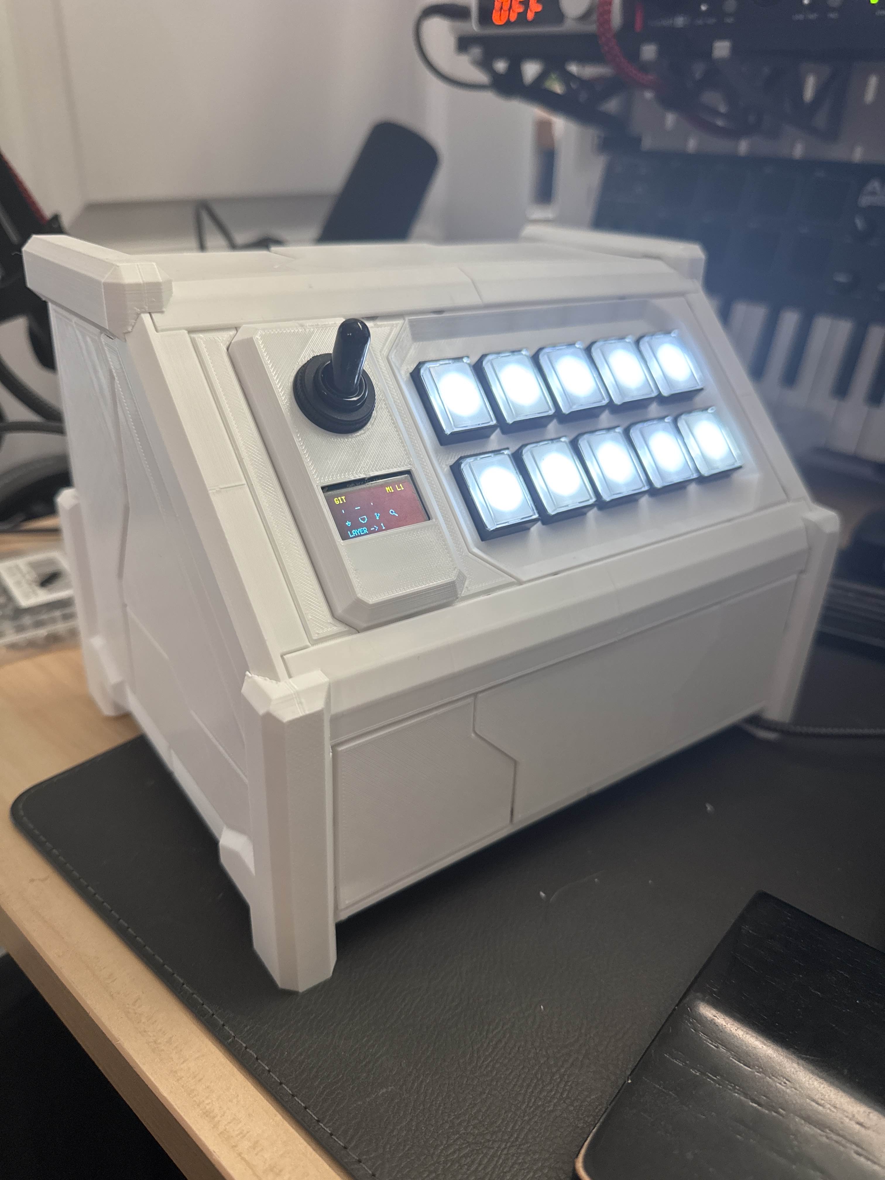
I have been working on a macropad that lives somewhere between a mech and the Millennium Falcon. It is not really a full cyberdeck, because it is not an independent computer. It does have an RP2040 inside though, and I am choosing to ignore that distinction and call it a MECHADECK anyway.
This project was mostly an excuse to make a controller that looked ridiculous in a very specific way. I wanted something with armor panels, visible shaping, and the kind of panel lining you get on a Gundam model kit. At the same time, I wanted to avoid a lot of exposed hardware on the outside. So the design philosophy became very simple: cover the bolts, and make it look like a tiny spaceship cockpit.
The first design problems
I printed a few prototypes before I got anything I was happy with. That included one full-size flimsy frame that absolutely did not work, plus a few half-size test panels just to check proportions and tolerances.
Originally, I started with lap joints. That idea sounded cool, because I was still trying to make this thing mostly tool-less to assemble. In practice, it was miserable. The inner structure looked neat, but it was impossible to maintain well, and there was basically no chance it would ever tolerate the kinds of print variance I was getting.
That was the point where I gave up on the mostly tool-less idea. Bolts are cheap. My time is not. Once I accepted that, the whole project got easier.
Closing in on the shape
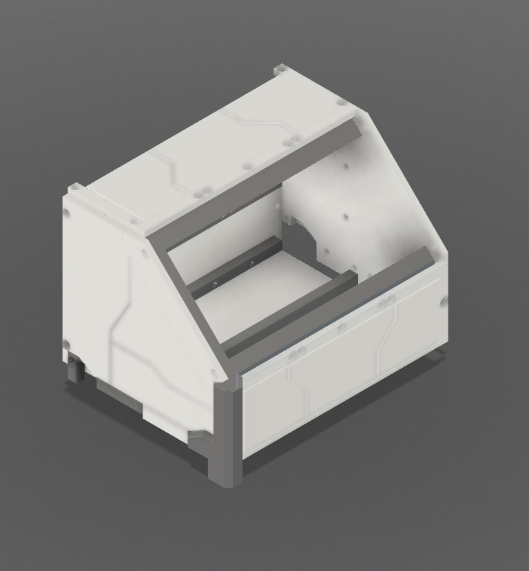
After abandoning the lap-joint plan, the project started turning into something much more realistic. I kept iterating on the shell shape, the panel layout, and the way the armor pieces covered the structure underneath.
This was the part where it finally started looking like the thing I had in my head instead of just looking like a CAD mistake.
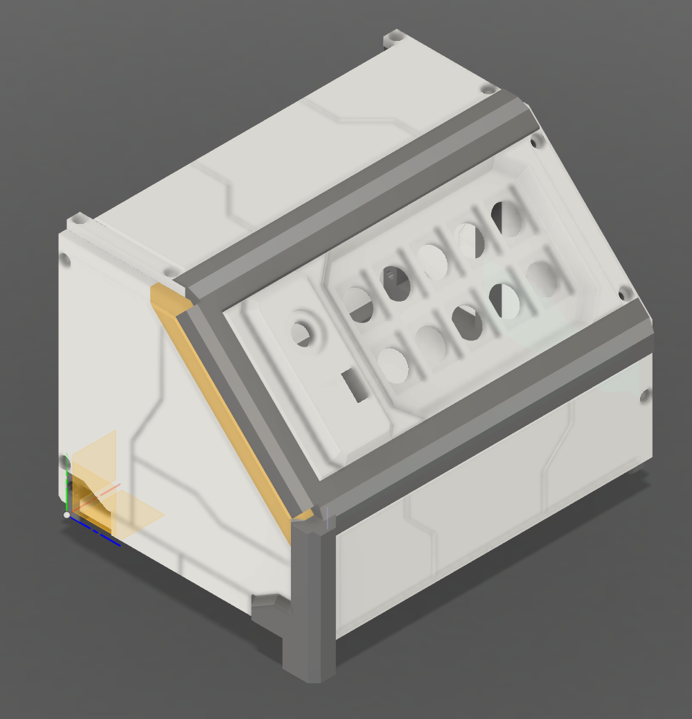
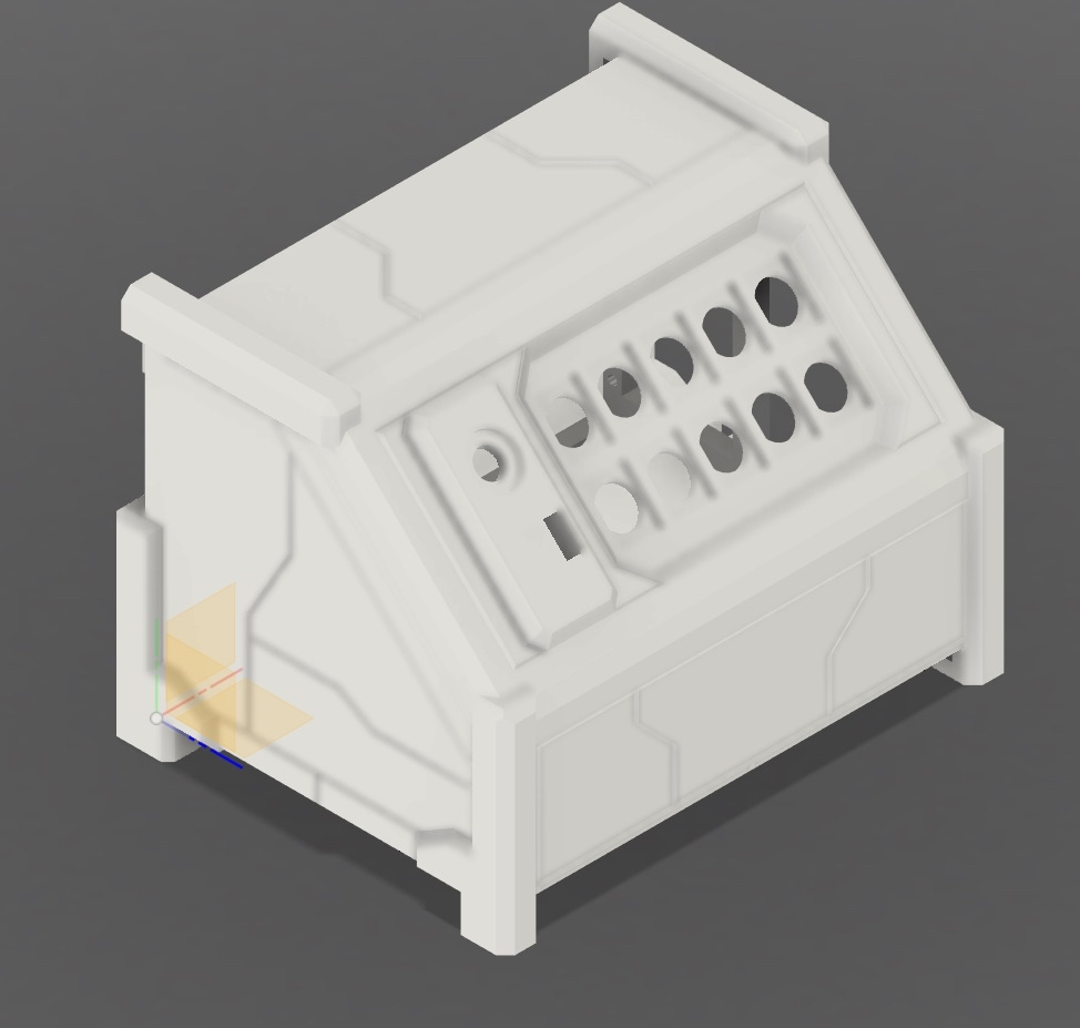
Once the general layout was right, I moved into full printing. That is always the point where you find out whether your cool idea actually exists or whether it was only valid inside a modeling program.
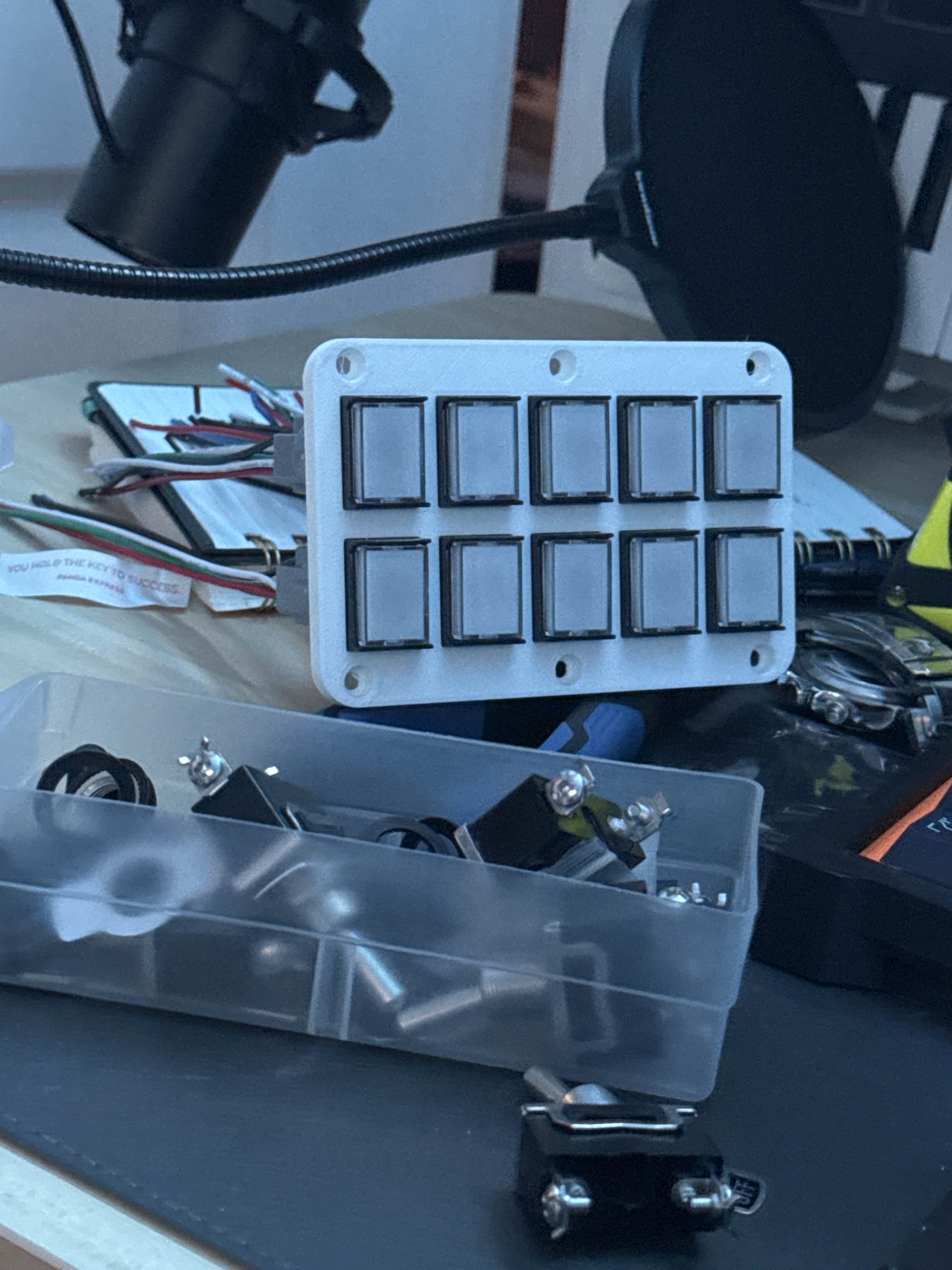
Buttons, layers, and firmware
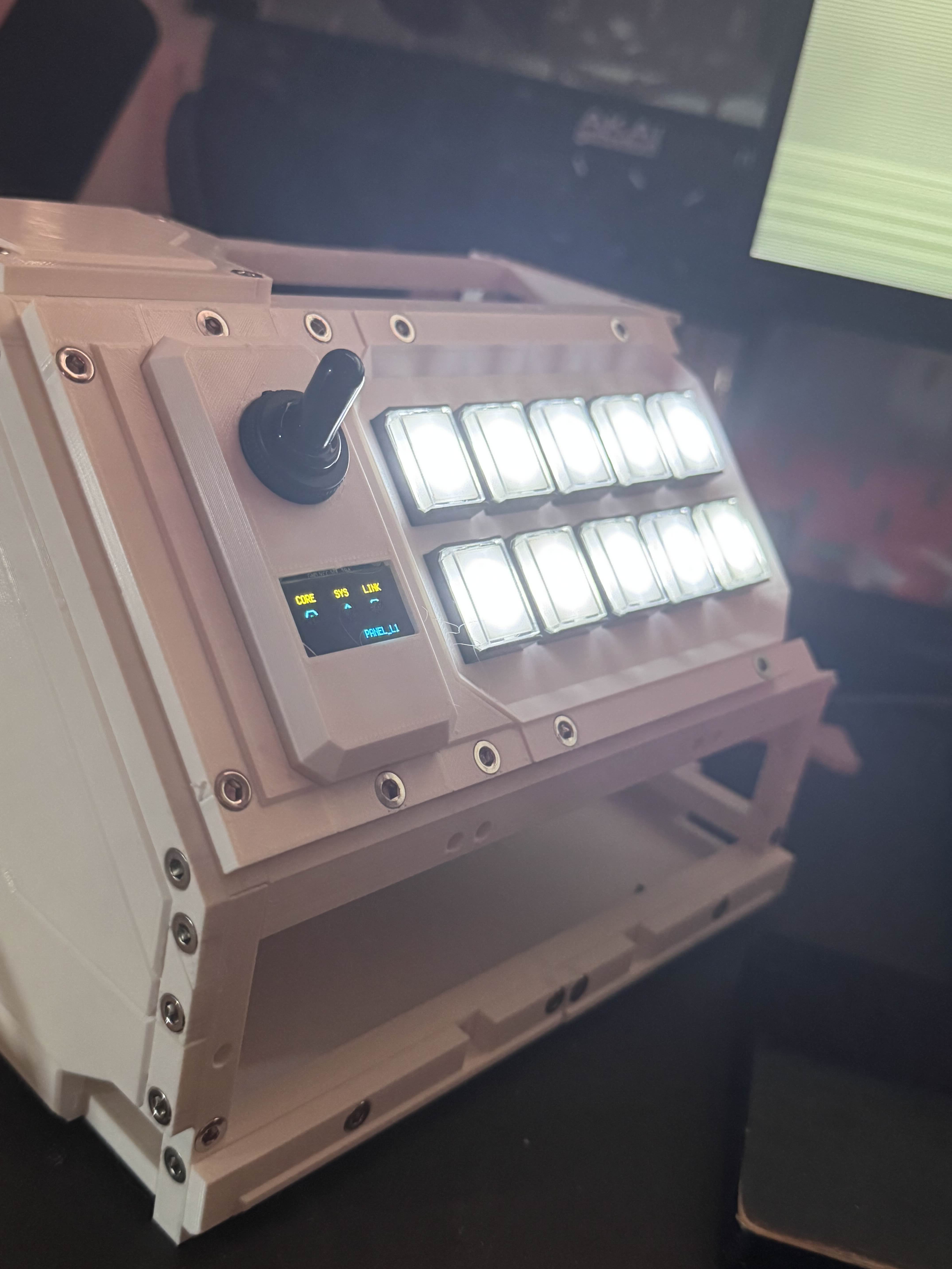
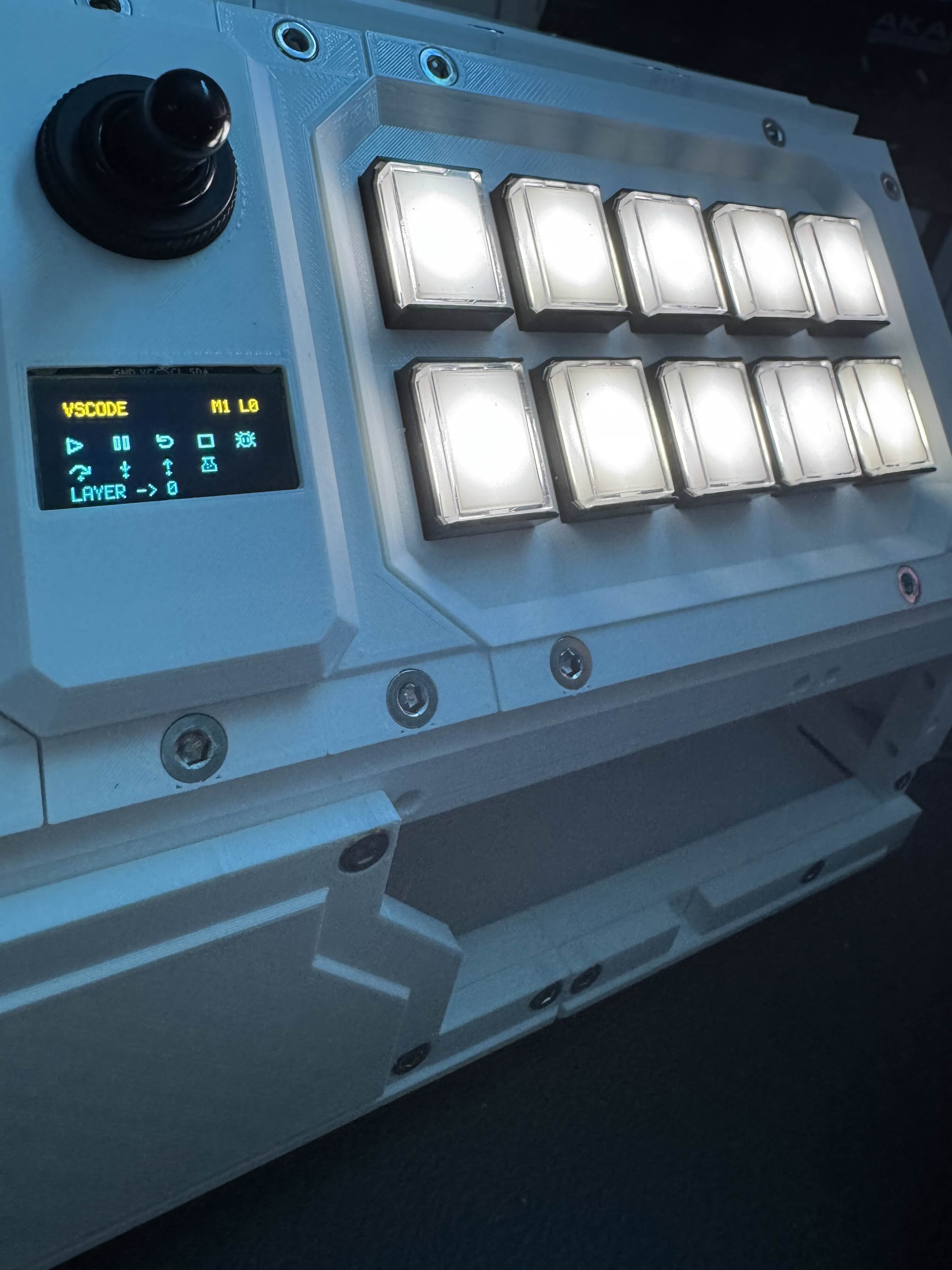
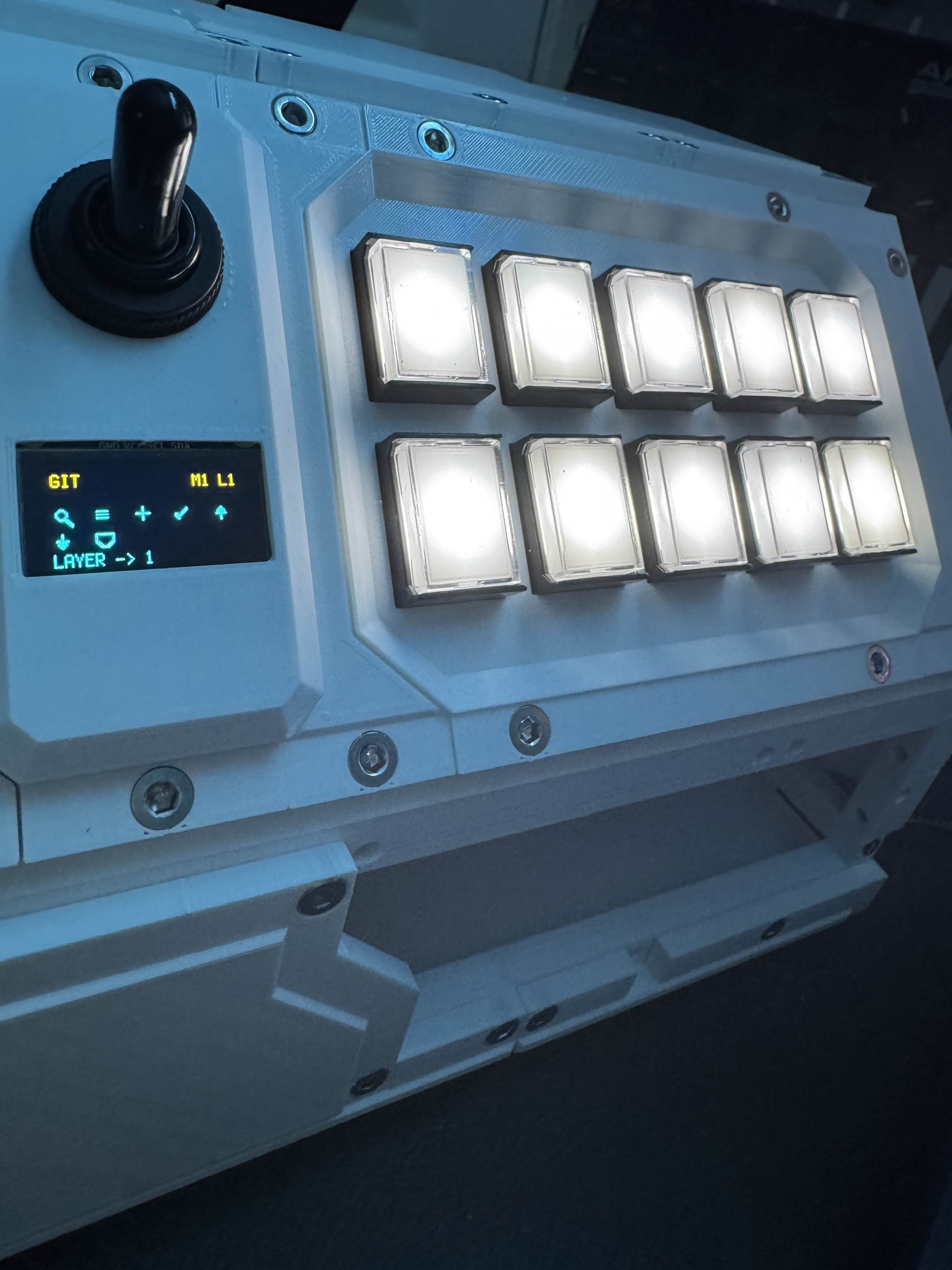
Eventually I got to the fun part: making it actually work. The first button test succeeded, which is always a good feeling when a project has spent most of its life being plastic problems instead of electronics problems.
The pad has ten buttons. There is a toggle that changes the control layer, and a long press on a button changes the mode. Each mode has two layers, which gives me a total of twenty different layers, each with up to ten commands.
That is a lot of utility packed into a weird little machine.
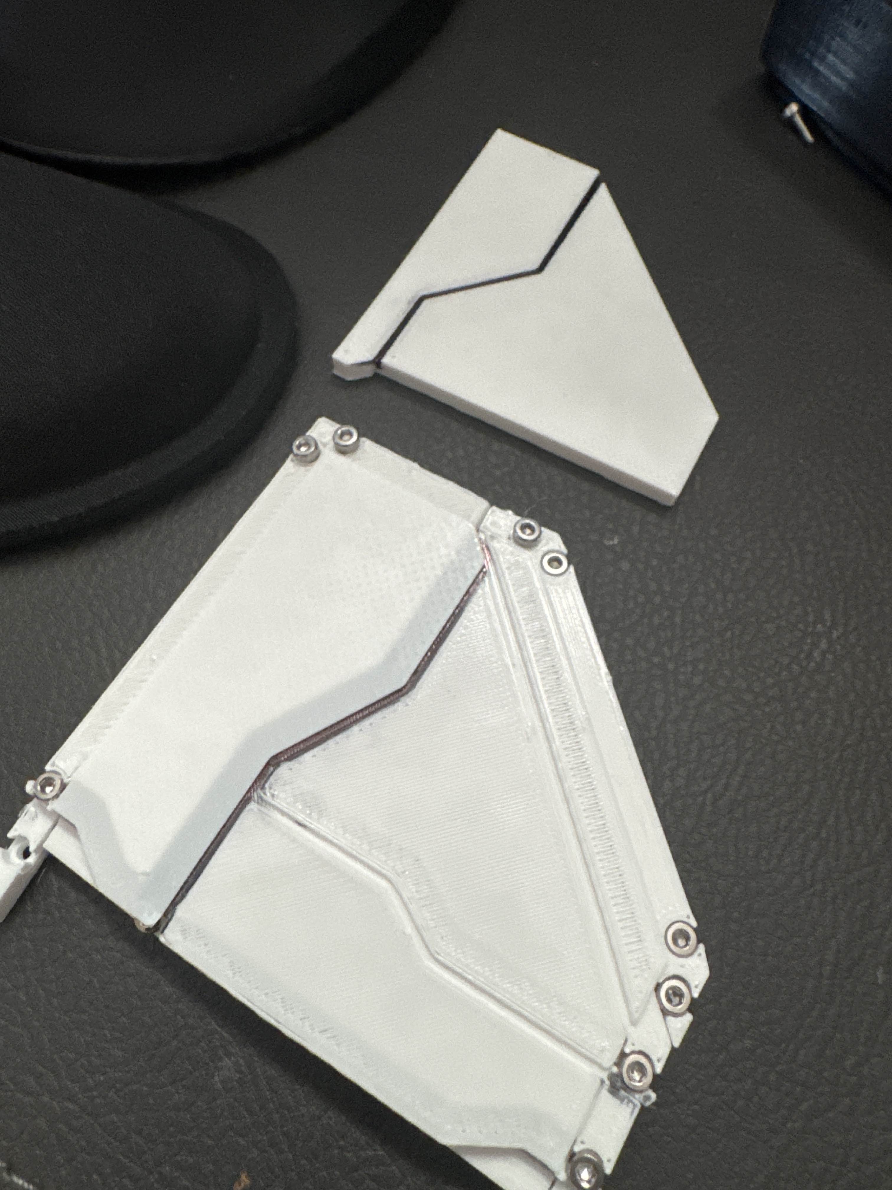
Armor panels and ugly guts
One of the most satisfying parts of this project was getting the bolt-cover panels right. That was a major aesthetic goal from the beginning, and once those started printing cleanly the whole build came together.
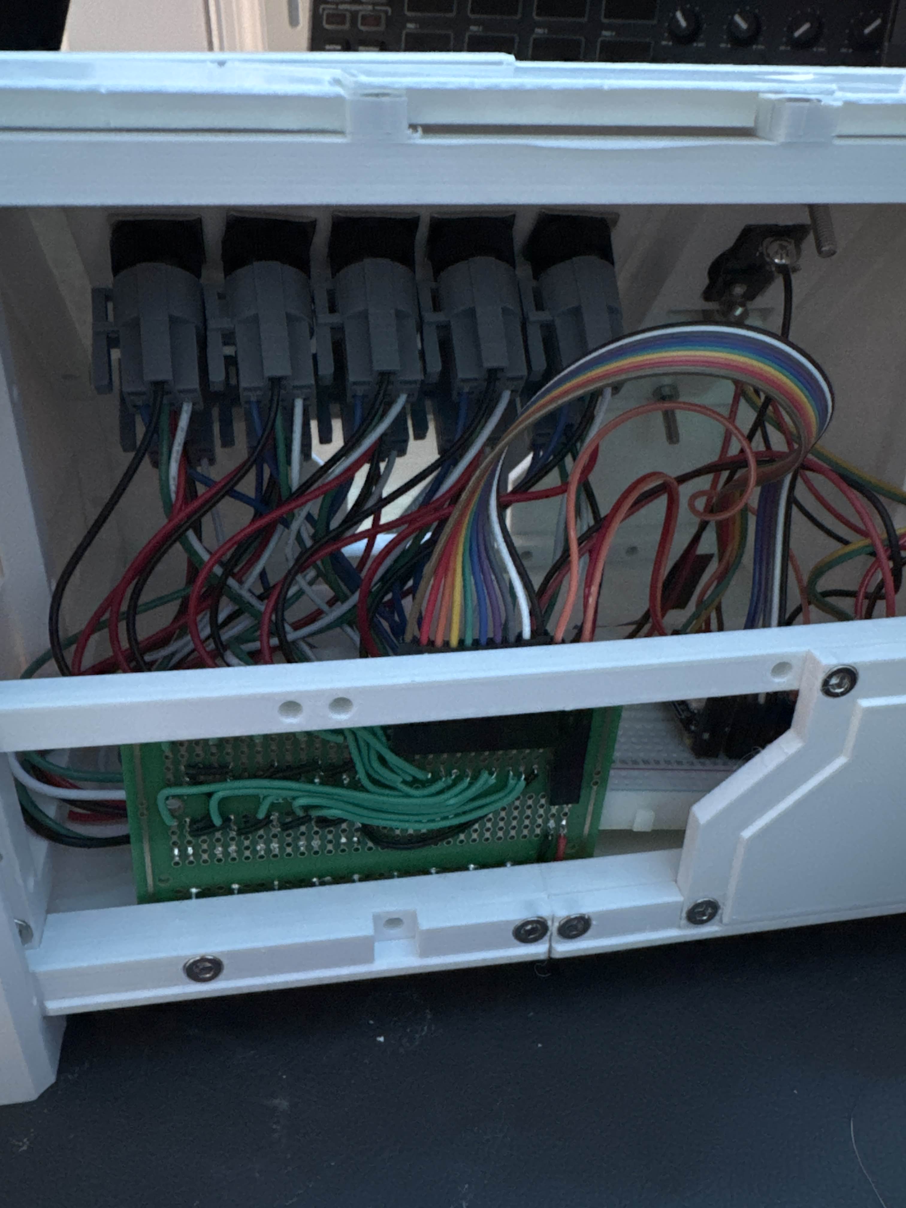
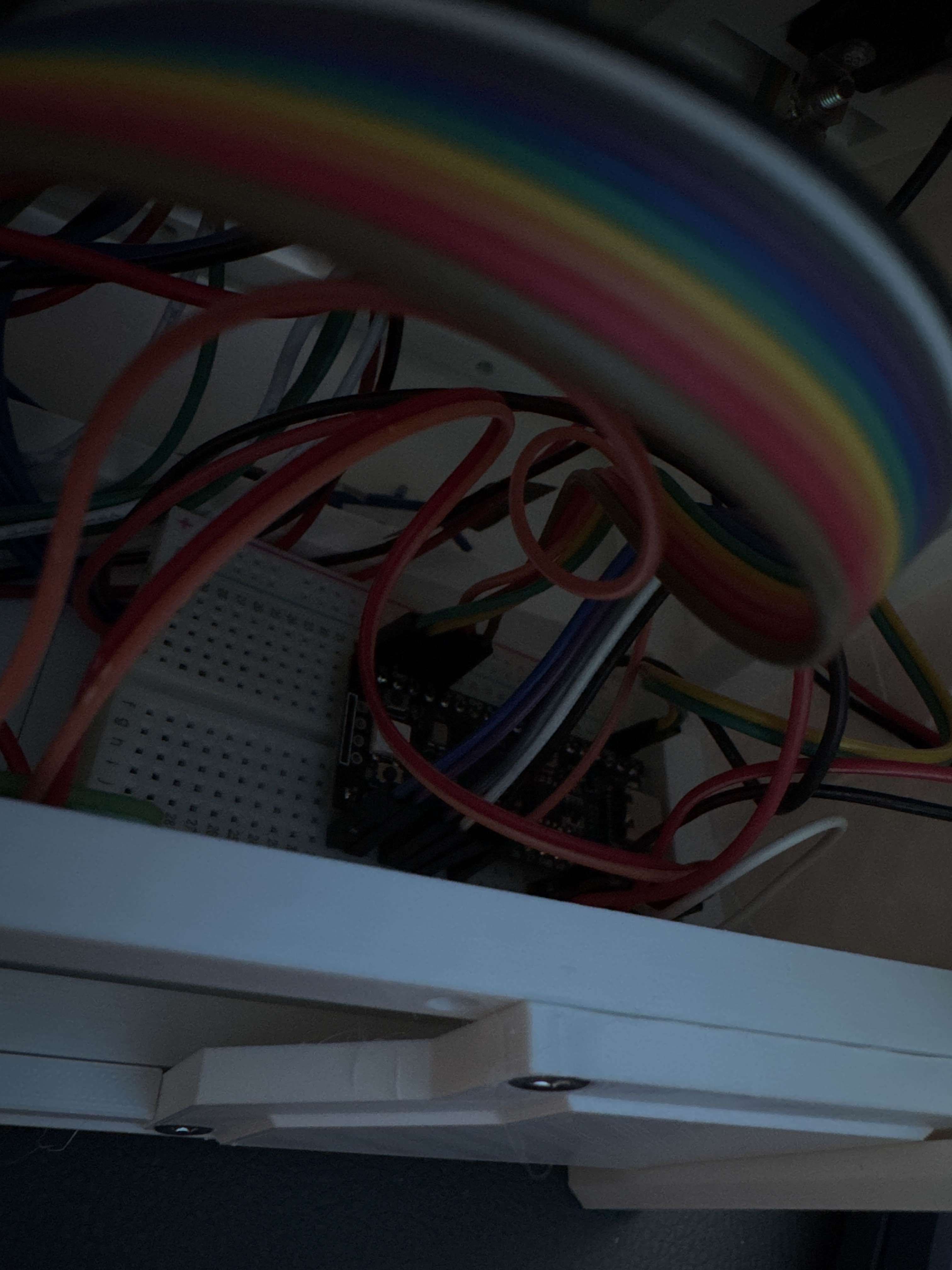
Someone asked me whether the weight distribution was weird, because the top of the device looks heavy. It actually feels pretty even in the hand. Most of the weight is just PLA. The inside is ugly, but it is honest ugly, and I can live with that.
I also planned the back so it can be removed quickly for access. That part mattered to me, because I did not want this to become one of those sealed projects that looks cool until the exact moment it needs one tiny repair.
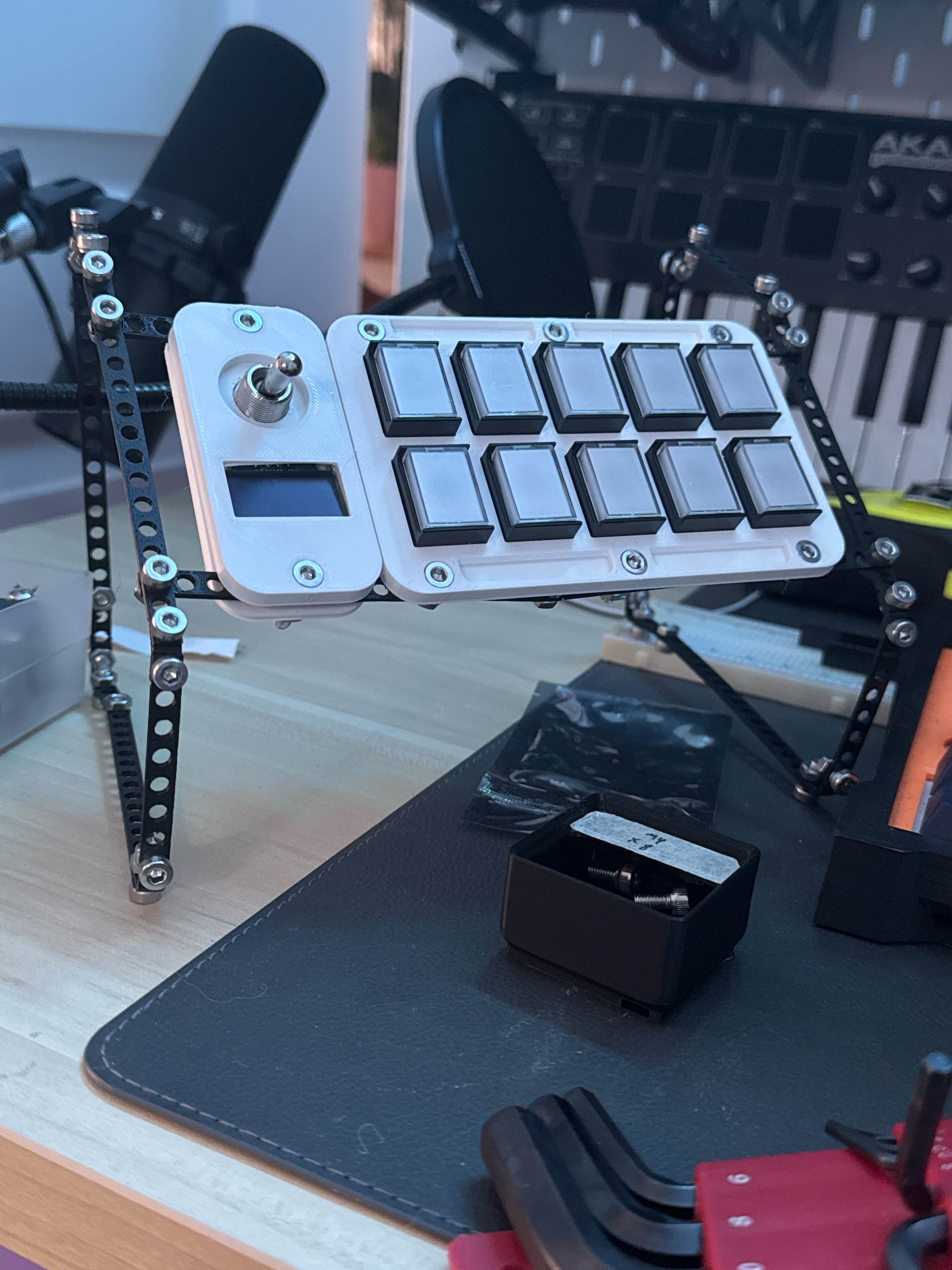
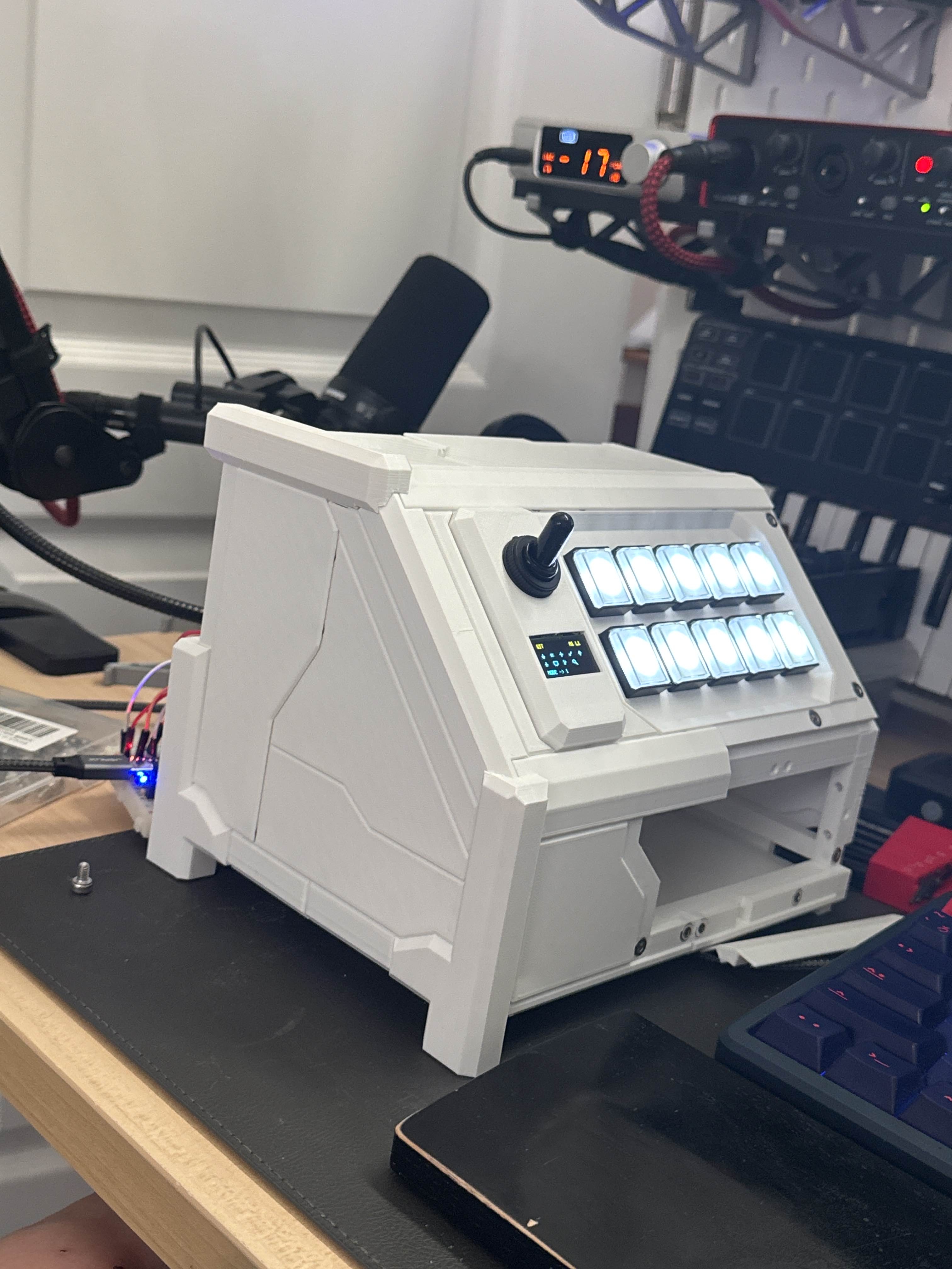
Final armor
By the time the final armor was printed, the thing had properly crossed over from prototype to object. I was considering adding a small drawer at one point, because apparently I cannot leave well enough alone, but the core build was done.
At that stage I was planning to share STLs, parts, and firmware right away. I ended up holding off on the firmware, because I realized I was in the middle of making it much better.
What happens next
The firmware is heading toward a more configurable setup instead of being overly specific to this exact device. Now that I am learning more parametric design, I also know how I want to improve the model itself. And because I apparently enjoy scope creep, I also want to make a PCB for it.
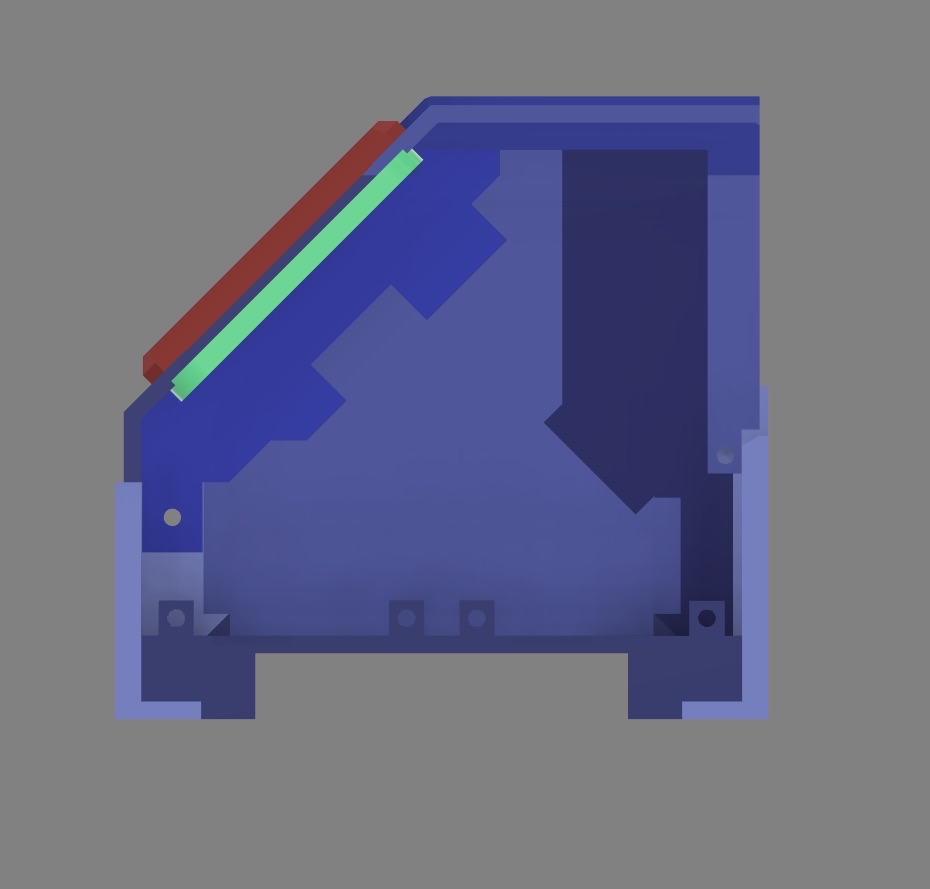
There is one ergonomic problem I definitely want to fix in a later revision. The usage angle is too high for something that gets used constantly. At around forty-five degrees, it looks cool, but it is better as an occasional-use pad than as something I would want to hammer on all day.
So this version is the cool one. The next version should be the practical one.
When I post the repo and the images for this properly, I will link those here too.